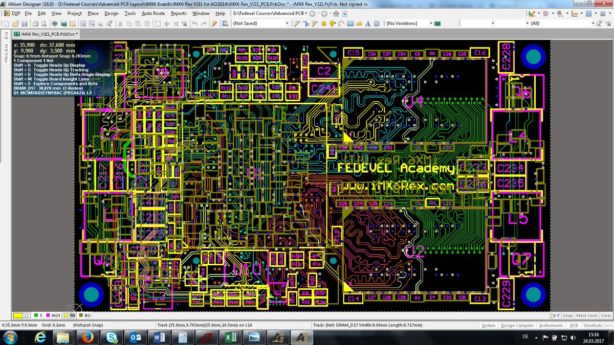


Render a PCB in real world graphics, that the colours are true to life, and I do/have used a few in my 40 years as a PCB designer. ZofzPCB, as the 3D Gerber viewer is known by, is the first free to use software package I have come accross that can So you can just change the minimum clearance value to o lower value that suits your case.After a chance reading of an article in theĮlectronics Weekly magazine on 22nd October 2014 of a 3D Gerber viewer, I decided to investigate further, as being a CAD/CAM centred design engineer,ĭiscovering a new approach to visualising data is always welcome.Īt what was then, an early stage of development, it was well advanced enough to be useable, not just as a viewerīut also in my case to generate real world graphics files, I need as an intermediate stage between E-CAD and M-CAD. If you found it from a library and put it directly, I think these are the correct dimensions. If you drew the footprint of the component yourself, check it once more. However in your case, it is seen that violated distances are belong to the pads of the footprint of component U1. Normally, you should check whether the PCB manufacturer can draw PCB with your defined minimum clearance values or not. You can redefine it from the settings that are defined in Design/Rules. In your case it is defined as 0.254 mm and I think it is the default value. This is called as minimum clearance value between nets.

In your case, one rule seems to be defined as "the distance between two layers that are connected to different nets should at least be greater than 0.254 mm". This wizard tell you if you violate any pre-defined design rules or not. I looked at your PCB, error is due to the "design rule check" wizard.


 0 kommentar(er)
